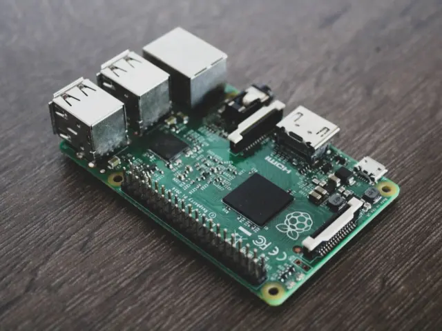
Wired your module and got a black screen? An OLED display on Raspberry Pi with Python needs four connections, I2C switched on, the Adafruit SSD1306 library and a Pillow drawing step. A blank panel usually means one of those is missing.
This walkthrough takes a bare SSD1306 module from wiring to its first text and shapes. It is a general setup guide; once it works, the raspberry pi gpio projects collection shows where to take it next.
Four assumptions that cause most failed setups
First-time builds rarely fail because of the code. They fail because the wiring, the operating-system setting or the Python environment does not match what the script expects. The table contrasts the common assumptions with what the setup actually requires.
| Common assumption | What actually applies | Planning use |
|---|---|---|
| Any free GPIO pins will carry the display signals | I2C data uses GPIO 2 on physical Pin 3 and the clock uses GPIO 3 on physical Pin 5 | Wire SDA and SCL to exactly those header positions |
| Connecting the wires is enough | I2C is enabled under Interfacing Options > I2C, followed by a reboot | Switch it on before blaming the module |
| The library can be installed with a bare pip command | The virtual Python environment must be active first, and the library relies on Blinka | Activate the environment, then install |
| The SSD1306 library draws text by itself | Pillow supplies the image processing; the library sends the finished picture to the screen | Install both and draw on a Pillow image |
These points come from the PicoBricks OLED guide and the SunFounder OLED lesson.
Wiring the module over I2C
A typical I2C OLED has four pins: GND, VCC, SCL and SDA. The PicoBricks guide, which uses a Raspberry Pi 3, maps them to the header as follows.
- VCC to 3.3V: use Pin 1 or Pin 17 to power the display.
- GND to ground: Pin 6, 9, 14, 20 or 25 all work, so pick the one closest to your other wires.
- SDA to GPIO 2: physical Pin 3 carries the serial data line.
- SCL to GPIO 3: physical Pin 5 carries the serial clock.
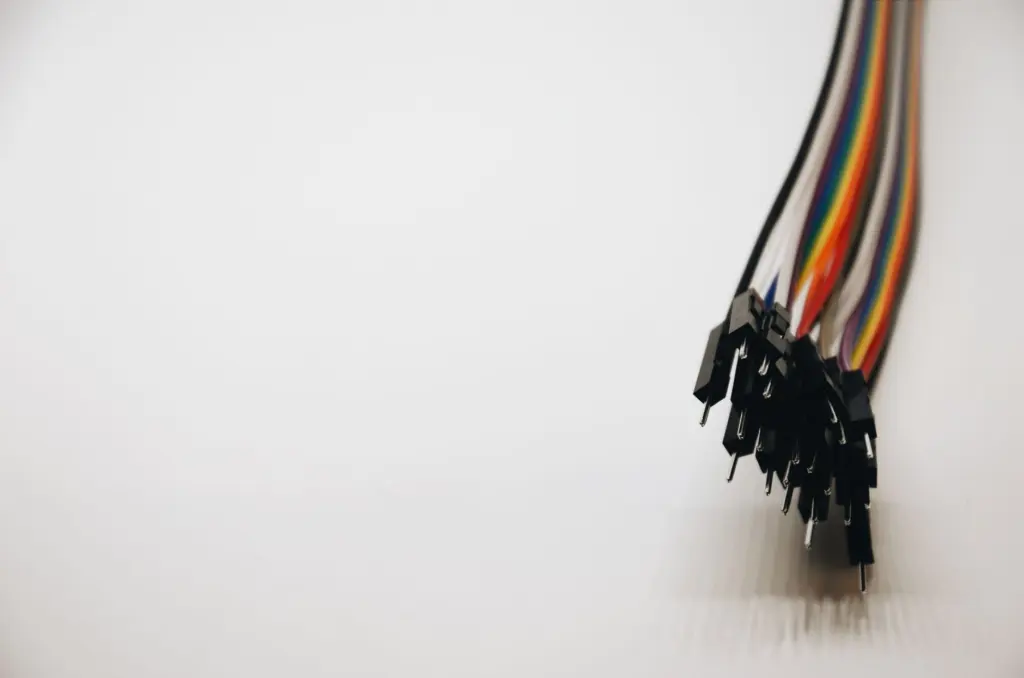
Power the Pi off before moving wires. Crossing SDA and SCL is the most common wiring slip, because the labels on small modules are easy to misread. Female-ended jumper wires suit most modules, provided the module header pins are already soldered.
Enabling I2C and detecting the display
The bus is off by default in the sense that you must switch it on. Open the configuration tool with sudo raspi-config, choose Interfacing Options > I2C, enable it and reboot, as the PicoBricks guide describes.
Next install the detection utility with sudo apt-get install -y i2c-tools. Then run i2cdetect with the -y flag and the bus number of the header I2C pins. A working SSD1306 module appears as an address in the grid. The SunFounder example uses addr = 0x3C with a 128×64 display, so expect to see 3c in the scan.
If the grid is empty, nothing below will help until the display answers the scan. Go to the checklist near the end of this guide before touching any Python.
Installing the Python libraries
Adafruit’s learning guide says its CircuitPython module lets you write Python code to control the display. For the SSD1306 that means the adafruit-circuitpython-ssd1306 package.
- Activate your virtual Python environment. SunFounder’s lesson stresses that it must be active before you install the library.
- Confirm Blinka is installed, because the SSD1306 library relies on it.
- Run pip install adafruit-circuitpython-ssd1306.
- Install Pillow in the same environment, for example with pip install pillow, so the script can draw.
Installing into the wrong environment is the usual reason a script that looks right fails with an import error. Run the script with the same environment active.
Drawing text and shapes
The SunFounder lesson explains that Pillow, the Python Imaging Library, adds image processing to your Python interpreter. The pattern is to draw onto a Pillow image and then hand that image to the display.
- Import board, adafruit_ssd1306 and, from PIL, Image, ImageDraw and ImageFont.
- Set WIDTH and HEIGHT to match your panel, then create the bus with i2c = board.I2C().
- Create the display with oled = adafruit_ssd1306.SSD1306_I2C(WIDTH, HEIGHT, i2c, addr=0x3C).
- Create a blank black-and-white Pillow image with Image.new, sized WIDTH by HEIGHT, and wrap it with draw = ImageDraw.Draw(image).
- Draw a shape such as draw.rectangle, then add text with draw.text((x, y), “Hello”, font=font, fill=”white”), loading the font with ImageFont.load_default().
- Send the picture with oled.image(image) followed by oled.show().
The TinyCircuits tutorial for the same hardware family demonstrates pixels, lines, shapes and text as its display basics. Its 0.96-inch, 128×64 panel is a useful reference for how much fits on screen: a few short lines of text, not a paragraph.
Blank screen checklist
Work through these checks in order, since each one rules out a layer beneath the next.
- Scan first: if i2cdetect shows nothing, the fault is physical or the bus is disabled. Recheck that I2C was enabled and that the Pi was rebooted afterwards.
- Swap SDA and SCL back: confirm SDA sits on Pin 3 and SCL on Pin 5, and that VCC goes to a 3.3V pin rather than a signal pin.
- Reseat loose pins: a joint that is not making contact can pass power but lose data, so press every header and check the solder on the module.
- Match the address: the addr value in the script must equal the address the scan reports. The SunFounder example uses 0x3C.
- Check the environment: import errors mean the libraries went into a different virtual environment from the one running the script.
- Consider a reset line: TinyCircuits notes a reset line may be required if the module has no auto-reset circuitry.
I2C and SPI versions of the module
The SSD1306 controller appears on modules with different connections. The PicoBricks guide notes that OLED screens attach by GPIO, I2C, SPI or USB depending on the model. The I2C version is the easiest to start with because it needs only the four pins above and shares the two bus lines with other I2C devices.
Check the pin labels on your module before buying jumper wires. If it shows SCL and SDA, follow this guide. If it carries labels from an SPI layout, the wiring table here does not apply, and the library setup needs a different display class from the I2C one used above.
Frequently asked questions
| Question | Answer |
|---|---|
| How do I clear the screen between updates? | Fill the display with zeros, which turns it black, then call show. Redraw your content afterwards. |
| How do I centre text? | Measure it first. The SunFounder lesson calculates the text size in pixels with font.getbbox, which you can compare against the display width and height to work out x and y. |
| What is Pillow used for here? | It adds image-processing capability to Python, so you can draw text and shapes onto an image that the SSD1306 library then sends to the panel. |