A robot that twitches, resets or veers off when the phone sends a command usually has a wiring or power fault. A wifi smartphone controlled two-wheeled robot works when the serial link, PWM pins and motor wiring are right.
This build pairs an Arduino Uno, an ESP8266 and an L298N driver, and it suits anyone moving on from basic sketches in our collection of arduino robotics projects. The sections below correct the usual misunderstandings in the order you meet them while building.
Parts and chassis
The build needs a small set of parts, and each has one job. The ESP8266 is the only addition to a standard L298N robot-car wiring scheme, according to the Electroniclinic robot-car walkthrough. So if you already have a wired Arduino car, you are most of the way there.
- Controller board: an Arduino Uno, which the reference build lists as its robot-car board.
- WiFi module: an ESP8266, which receives phone commands and passes them to the Uno.
- Motor driver: an L298N module with two motor channels, one per wheel.
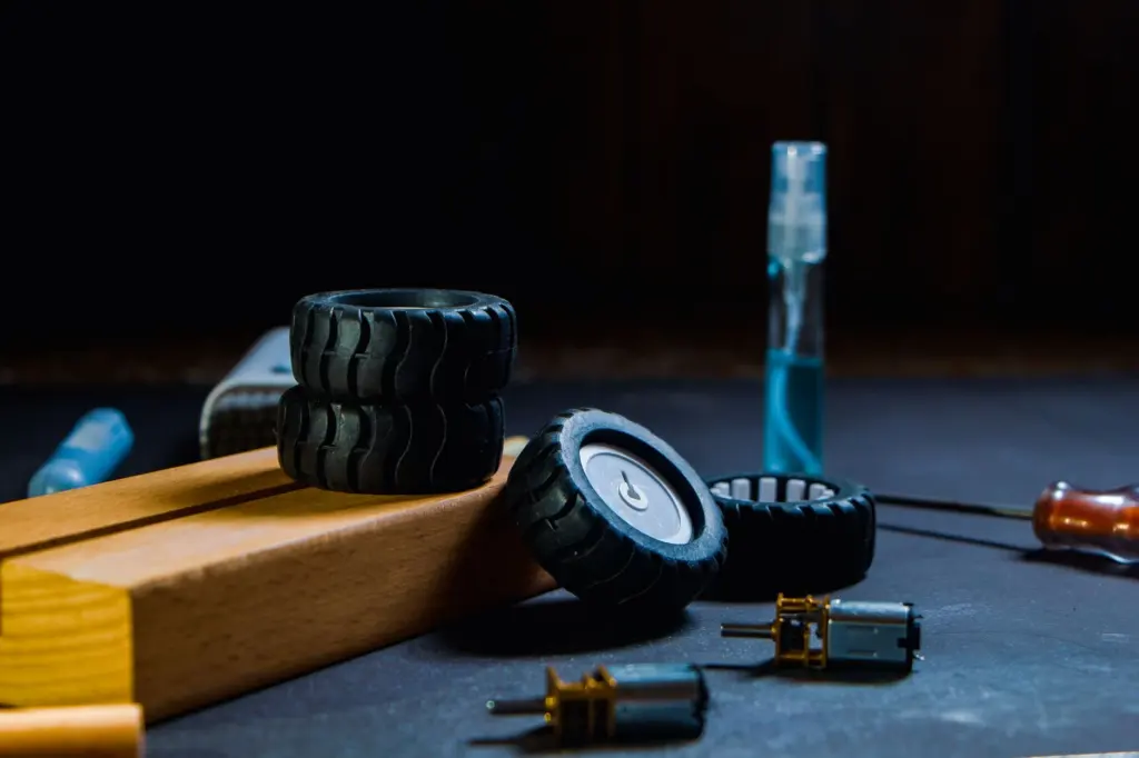
- Drive hardware: two DC gear motors with wheels, mounted on a robot-car chassis kit.
- Balance point: a caster wheel, which is passive and can move in any direction, so it follows the drive wheels without steering.
- Battery pack: a holder sized for your motors, kept separate from the module supply as described in the power section.
Stability comes from geometry. The STEMpedia smartphone robot project notes that a robot needs at least 3 contact points with the surface, which is why two drive wheels plus a caster is the usual layout. Route the motor wires inside the bracket, because wires left outside can catch on the wheel.
How the phone sends drive commands
The phone never drives the motors directly. It sends control values over your local WiFi network to the ESP8266, which forwards them over a serial line to the Uno, and the Uno turns them into pin signals for the L298N.
In the reference build, a Blynk joystick widget handles forward, reverse, left and right, while a slider widget sets motor speed in real time. The values travel as one comma-separated text string covering left, forward and speed. The Uno sketch splits that string at each comma and uses the pieces to set direction pins and speed. A browser page with forward, back, left and right buttons can play the same role if the ESP8266 sketch converts each button press into the same kind of text values. The Uno side stays identical either way.
| Common assumption | What actually happens | Planning use |
|---|---|---|
| The phone talks straight to the motor driver. | The ESP8266 receives the commands and passes them on over serial. The Uno drives the L298N. | Debug in stages: phone to module, module to Uno, Uno to driver. |
| Speed needs its own control path. | Speed arrives in the same comma-separated string as direction. | One parsing routine on the Uno handles both. |
| Any Uno pin can set motor speed. | Speed is set by PWM on the L298N enable pins, wired to Arduino pins 5 and 6. | Keep those two pins free of other uses. |
| The ESP8266 is a bolt-on that changes the motor wiring. | It is the only change to an existing L298N robot-car wiring scheme. | Reuse a working wired car and add the module last. |
The comparisons above follow the pin and parsing choices in the Electroniclinic NodeMCU robot-car build.
Wiring the ESP8266 to the Uno
Serial pins and baud rate
Connect the ESP8266 TX line to Arduino pin 2, as the reference build does. The Uno listens on that pin through a software serial port, so the hardware serial port stays free for uploading and debugging. Start the software serial link at 9600 baud, and use the same rate in the ESP8266 sketch.
Handling the voltage difference
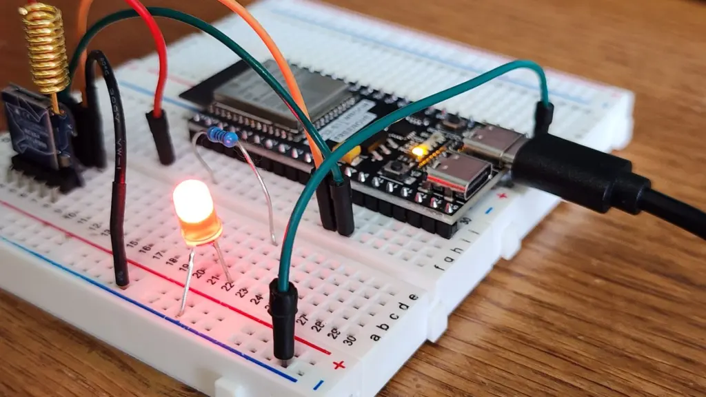
The ESP8266 is a lower-voltage part than the Uno, so treat the signal going into the module with care. The line that needs protection is the one carrying the Uno’s output into the ESP8266 input. Put a resistor divider on that line, or use a level-shifter board, and confirm the safe input level in Espressif’s datasheet for your exact module. The line from the module into the Uno is the one the reference build wires directly.
Do not skip this step because the circuit appears to work. Overvoltage can degrade a module over time rather than fail at once, and a module that dies later is hard to diagnose.
Wiring the L298N for direction and speed
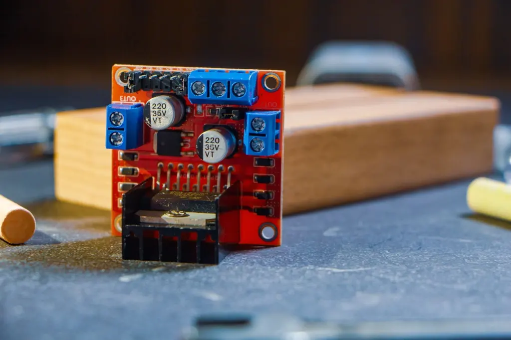
The L298N needs six control connections from the Uno, and the pin choice matters for speed control. Wire the two enable pins to Arduino pins 5 and 6, then the four direction inputs to pins 8, 9, 10 and 11, as in the reference code (in1 to in4).
- Enable pins (5 and 6): these carry the speed. The sketch calls analogWrite on them, which produces the pulse width modulation that sets motor speed. Using PWM-capable pins is what makes the slider work.
- Input pins (8 to 11): each motor gets a pair. Setting one high and the other low picks the direction, and swapping them reverses it.
- Motor terminals: one motor on each output block of the driver, with wires routed so they cannot touch the wheels.
Powering motors and ESP8266 without resets
Give the motors their own battery pack and keep the ESP8266 on a steady supply of its own. Motors draw uneven current as they start, stop and reverse, and a module sharing that supply can brown out and restart. The robot then seems to ignore the phone just as you press a button.
The reference demonstration powers the ESP8266 from a laptop during testing, which keeps it away from motor noise while you debug the code. For a free-roaming robot, replace the laptop with a small regulated supply for the module. Connect the grounds of the battery pack, the driver, the Uno and the module, because a missing common ground produces erratic commands that look like software faults.
Be careful with more battery voltage. The STEMpedia project says extra batteries can speed up the robot, but check any increase against the ratings of your motors and driver first. A reset that starts only when you push the slider up points to supply sag rather than a code problem.
Fixing curves and wrong-way driving
When the robot curves or steers backwards, the cause is almost always a wheel doing something different from its partner. Equal wheel speeds in the same direction drive the robot in a straight line, so any drift means one side differs in direction, speed or both.
- One wheel runs backwards: the STEMpedia project says that backward or turning motion on a forward command means at least one motor is rotating the wrong way. Fix it by reversing that motor, either by swapping its two wires at the terminal block or by swapping its two input pins in the sketch.
- One wheel never stops: in the reference stop branch, the code writes in3 low twice and never clears in4. One motor can therefore keep a direction signal when the joystick returns to rest. Set both in3 and in4 low, and check the in1 and in2 pair the same way.
- Uneven speed: make sure both enable pins receive the same speed value. A slider that only reaches one channel makes the robot pull to one side.
- Drag from the chassis: a loose motor wire against a wheel slows one side. Re-route it inside the bracket.
Change one thing at a time, then lift the robot off the bench and test each command before putting it on the floor.
Frequently asked questions
| Question | Answer |
|---|---|
| Does the old Blynk 1.0 app still work? | No. The reference build notes that the old version of the Blynk app is no longer functional, so use the current Blynk app or a browser page that sends the same values. |
| How do I make the robot turn on the spot? | Drive both wheels at equal speeds in opposite directions. In the STEMpedia project, this rotates the robot in place, and the drive wheels pivot around the middle. |
| What should the joystick do when released? | It should stop both motors. In the reference sketch, the centre position sets both enable values to 0, so the robot stays still until a new command arrives. |